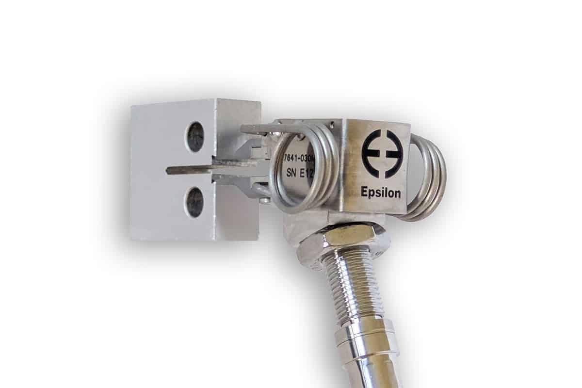
High Temperature Clip-On Gages (700 °C) – Model 7641

Gen3 Product
Recent 7641 COD Gage improvements:
- Fit tighter spaces and a wider variety of specimen designs
- More creep-resistant, high-temp tip material
- Updated groove geometry – extended tips are now standard
- Improved overtravel protection & mechanical robustness
- New / additional configuration options for fitment in tight spaces
- Increased margin for specimen variation
- Armored high-temperature cable
With verifiable CALIBRATION SYSTEM ACCURACY and resolution sufficient to meet the requirements of ASTM fracture toughness gages, you can be assured that your COD gages will perform to your testing requirements.
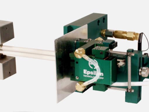
These COD gages use a high-temperature capacitive sensor and do not require any cooling. They will operate up to the maximum temperature limit of most environmental chambers used in materials testing. The Model 7641 is ideal for determination of fracture mechanics parameters such as JIC, KIC, R-curve, and fatigue crack growth rate (da/dN) using testing standards such as ISO 12135, ISO 12108, ASTM E1820, E399, and E647. The 7641 may be used as the feedback sensor for tests performed in closed-loop displacement control such as JIC.
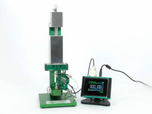
The COD gage is supplied with the advanced DT6229 controller. The standard output is a ±10VDC analog signal, factory calibrated with the COD gage. The controller also provides a high-speed digital output, built-in calibration and tare functions, and filters.
The 7641 is readily interfaced with most existing test controllers or may be directly connected to a data acquisition system or a PC.
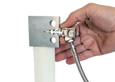
Recent design upgrades include improved overtravel protection; enhanced mounting tips that accommodate more specimen geometries, while also improving handheld ergonomics and ease of installation; and an attachment point for a tether or counterbalance. Model 7641 is available in whole-millimeter gauge lengths ranging from 3 – 12 mm with a variety of measuring ranges.
- May be left on through specimen failure.
- All standard models are suitable for cyclic testing.
- >10 Hz typical for 5mm GL and larger
- Typically limited by the user’s test apparatus, specimen, and test method
- Digital controller and power supply included. Provides high level DC voltage output with low noise. Easily interfaced to test controllers, data acquisition boards and chart recorders.
- Includes high speed analog and digital outputs
- Intuitive web-based user interface for setup, calibration, and data acquisition
- Built-in calibration reference and auto-zero features
- Multiple extensometer calibration files may be loaded for use with one controller
- Multiple temperature-specific calibrations may be stored
- 11-point linearization
- Selectable analog and digital filter options from 2 Hz to 3 kHz
- Ships fully calibrated with electronics (traceable to NPL (UK)) with user-specified voltage output.
- Built-in mechanical stops prevent over-travel.
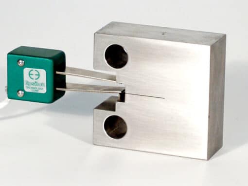
- Rugged, dual flexure design for strength and improved performance.
- All units can be displaced slightly in compression for ease of installation.
- Rugged, long-lasting high-temperature cable is armored to prevent kinking and pinching.
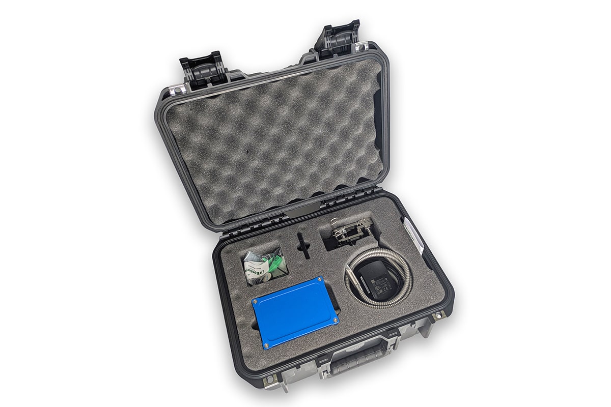
- Includes high quality foam lined case.
Analog Output: User specified, typically ±10V; ±10.8V rail
Digital Output: 24 bit high speed Ethernet output with built-in web interface
Accuracy: All standard configurations meet ASTM E1820, ISO 12135, ISO 9513 Class 0.5, and ASTM E399 (up to 3mm) requirements for accuracy. A test certificate is included.
Linearity: 11 point linearization, ≤0.15% FS typical linearity
Resolution: <55 PPM (0.006%FS) RMS @ 4 kHz, <6 PPM (0.0006%FS) @ 100 Hz
Cyclic Testing: Models available for 10-50Hz testing; see Model-selection-table
Analog Filter: Selectable 100 Hz analog and 2 Hz – 3 kHz digital filters
Temperature Range: Ambient to 700 °C (1300 °F). Springs may require periodic adjustment or replacement after long-term testing above ~600 °C.
Temperature Sensitivity (Gain): <100 PPM / °C (0.01%FS/°C) typical (see Temperature Sensitivity Compensation)
Sensor Cable: 0.7 m (2.5 ft) armored, tri-axial high temperature cable, plus 1.5 m (5 ft) room temperature extension cable
Output Cable: Flexible 2.4 m (8 ft) analog output cable
Operating Force: 10-50 N typical, depending on model
Environment: Recommended for elevated temperature testing in dry air or inert / non-corrosive gases
Overall Dimensions: Epsilon-model-7641-Gen3-outline-drawing.pdf
Power: Includes power supply with a plug for your country (specify)
![]()
- Connectors to interface to nearly any brand of test equipment
- Bulkhead adapters for vacuum chambers
- Bolt-on knife edges for attachment to test specimens without machined attachment points
-
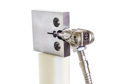
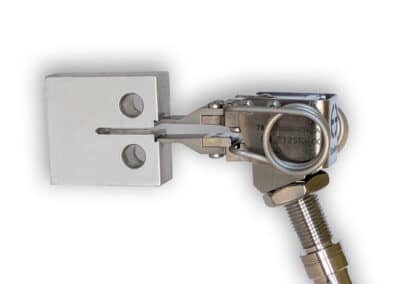
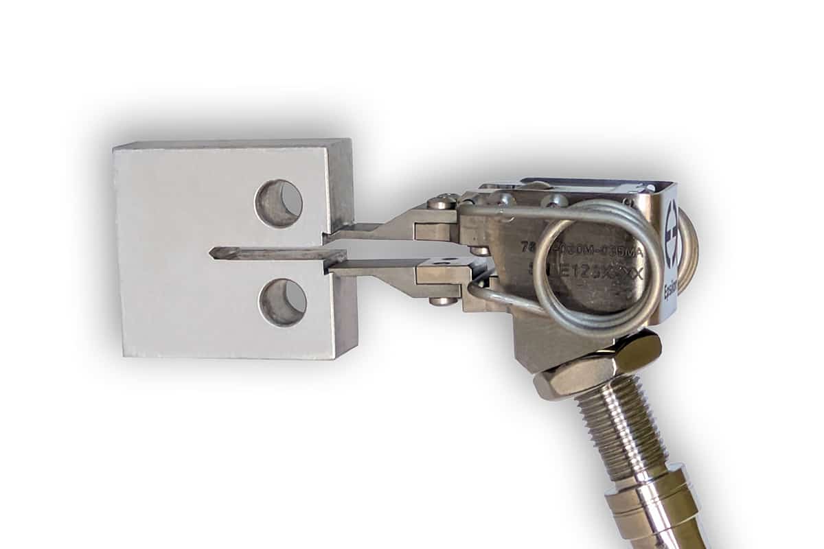
Model 7641 with integral load-line knife edges
-
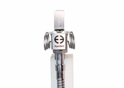
Model 7641 end view
-
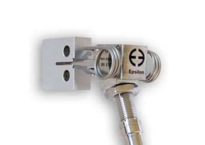
Model 7641 with integral load-line knife edges and clevis grips
-
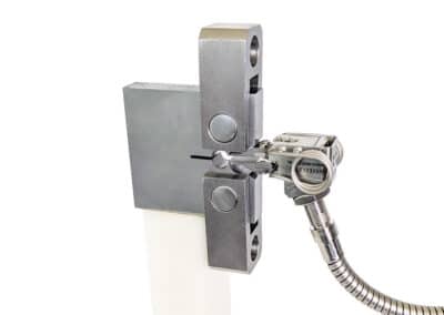
Model 7641 with integral front-face knife edges
-
Model 7641 with integral front-face knife edges
-
Model 7641 with integral load-line knife edges
-
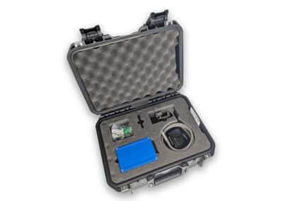
Storage case (model 7642 shown))


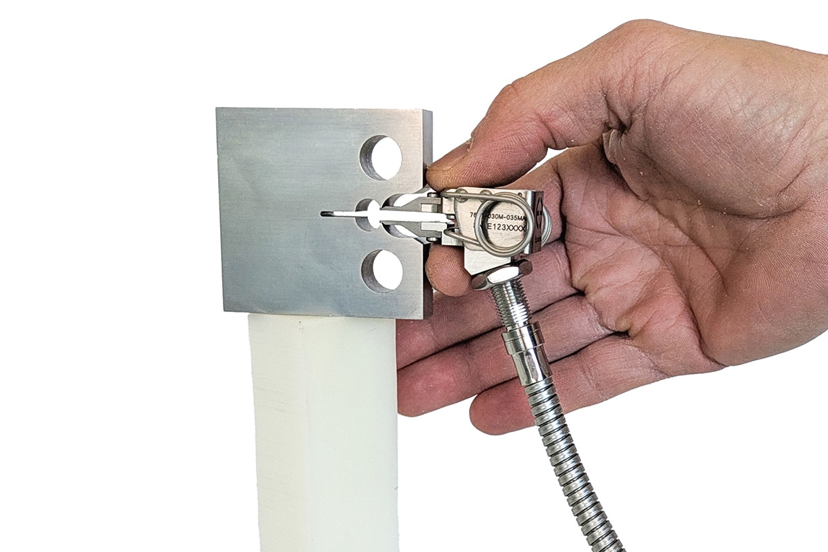
Make Sure It Fits Your Setup
1. Make sure that model 7641 fits your specimens, grips, and chamber/furnace
Follow these steps: pick a gauge length, pick a measuring range, and check to make sure that the model 7641 configuration you selected fits your specimen, grips, and chamber/furnace. Use these resources:
- Review this drawing: Epsilon-model-7641-Gen3-outline-drawing.pdf
- Review Contact Tip Detail CAD files:


2. Review the Model Selection Table
Check your selection of gauge length and measuring range for the maximum frequency and mounting stability: Model-selection-table
3. Having trouble fitting model 7641 with narrow CT specimens and narrow clevis grips?
When the grips or specimen are narrow, request this Tech Note: Epsilon Tech Note: Thin CT Specimens
Ordering Information
Click table options to configure
Gauge Lengths
| Gauge Length | Model |
|---|---|
| 3.0 mm(0.12in) | -030M |
| 4.0 mm(0.16in) | -040M |
| 5.0 mm(0.20in) | -050M |
| 6.0 mm(0.24in) | -060M |
| 7.0 mm(0.28in) | -070M |
| 8.0 mm(0.31in) | -080M |
| 9.0 mm(0.35in) | -090M |
| 10.0 mm(0.39in) | -100M |
| 11.0 mm(0.43in) | -110M |
| 12.0 mm(0.47in) | -120M |
Installed Gauge Length is set by your specimen. Round DOWN to the nearest available size.
Measuring Ranges
| Measuring Range | Model | Total Length |
|---|---|---|
| 5.5 mm(0.22in) | -055MV¹ | 47.6mm(1.88in) |
| 7.0 mm(0.28in) | -070MV² | 56.5mm(2.23in) |
| 8.0 mm(0.31in) | -080MV | 60.3mm(2.38in) |
| 9.0 mm(0.35in) | -090MV | 66.7mm(2.63in) |
| 3.5 mm(0.14in) | -035MA*¹ | 51.1mm(2.01in) |
| 4.5 mm(0.18in) | -045MA*² | 59.9mm(2.36in) |
| 5.0 mm(0.20in) | -050MA* | 63.8mm(2.51in) |
| 5.5 mm(0.22in) | -055MA* | 70.1mm(2.76in) |
* -xxxMA = angled cable exit
¹Best dynamics and stability; recommended for front face specimens
²Good dynamics and stability; best ergonomics; recommended for load line specimens
7641 Clearance Considerations

7641 Total Length and Ergonomics

Related Models
Repairs/Service
If your unit is in need of service, calibration or repair, initiate the RMA process with us and we will be happy to assist.
Get Our Newsletter
Sign up for our newsletter to get the most up-to-date information on products and services.
Download Catalog
Our 2025 Extensometer Catalog, Version 111 is now available! Not finding something you’re looking for? Ask us about a custom quote.